Projektsidor
NS 4713 – NOHAB littera M3b (Sida/Page 01)
Svenskt 7¼" ånglokomotiv byggs i Nederländerna
ZG 13 — NS 4713
{Delar / Parts 1—10}
———
|
Svensk export av ånglok till Nederländerna. ZG 13 godstågslok blir NS 4713. |
|
Export of Swedish steam locomotives to The Netherlands. ZG 13 freight locomotive becomes NS 4713. |
|
Våra två medlemmar Michiel van Gremberghe och George van Rooijen bygger tillsammans ett ånglok med spårvidden 7¼”. av en typ som ursrungligen tillverkades i Sverige för de Nederländska järnvägarna – NEDERLANDSCHE SPOORWEGEN. Loket är baserat på det svenska godstågsloket littera M3b och byggdes av Nydquist & Holm AB, (NOHAB), i Trollhättan. Beteckningen från Nohab för dessa exportlok Nohab tillverkade även en snälltågsvariant som i Sverige betecknades littera H3s och som för den Nederländska marknaden benämndes ZS 1–15. NEDERLANDSCHE SPOORWEGEN gav dem sedan beteckningen NS 4001–4015. |
|
Our two members Michiel van Gremberghe and George van Rooijen are constructing a steam locomotive in 7¼” gauge. This freight locomotive was originally made by Nydquist & Holm AB (NOHAB) in Trollättan, Sweden and based on the Swedish littera M3b. Nohab built these locomotives for export to NEDERLANDSCHE SPOORWEGEN. Express locomotives in the series ZS 1–15, These were identified as NS 4001–4015. |
Introduction by Michiel van Gremberghe and George van Rooijen.
Klicka på bilderna för större format. / Använd vänster pil för att återgå hit.
Click on the picture for a larger view. / Use left arrow to go back.
Bilder från George eller Michiel såvida inte annat noteras.
Photos from Georg or Michiel unless otherwise noted.
Del 1 — 2018-11-04 — Part 1
|
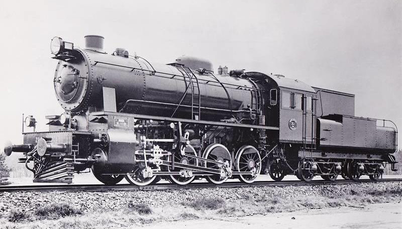
Bilder på olika lok i serien NS 4700. Photos of the series 4700 locomotive. GRj |
abc |
George och Michiel framför ett M3b-lok fotograferat i Grängesbergs Järnvägsmuseum.* George and Michiel in front of a M3b loco in Grängesbergs Railway Museum* in Sweden. |
|
Ovanstående lokbilder hämtade från nätet. Drawings from internet. |
abc |
Experimentmodell av NS 4713, visad vid vår tältutställning under ångdagarna 2018. Experimental model of the loco NS 4713. GR |
* Grängesbergs Järnvägsmuseum (se sidan 3) har ett lokomotiv litt. M3b under renovering,
likvärdigt med NS 4713, som skall byggas i modell av George och Michiel.
---------------------
* Grängesbergs Railway Museum (see page 3) is restoring a Swedish locomotive M3b,
which is of the same type as NS 4713, which will be built as a live steam model by George and Michiel.
———
Del 2 — 2018-12-04 — Part 2
|
När vi först började med projektet i december 2017, sökte vi genom 3D-modellen av loket och tendern. Vi letade efter delar som vi kunde tillverka på CNC-fräsen.Eftersom boggierna till tendern redan var byggda började vi tillverka delar för bromsanordningen för densamma.Till loket fräste vi bindjärnen för hornblocken och några tvärbalkar till ramen. För fjädrings-systemet tillverkade vi balansarmar och dessas upphängningsfästen. |
abc |
When we started the project in December 2017, we first searched the 3d model of the locomotive and tender for parts that we could make on the CNC milling machine.Because the bogies of the tender were already completely modeled, parts of the brake system were milled.For the locomotive, the horn stays and some cross brackets could be milled for the frame and for the spring system, the balance hinges and balances. |
|
Fräsarbete på en sida av ett bindjärn, detta vänds om för bearbetning av andra sidan. Milling a horn stay, which later is turned around |
abc |
Samtliga bilder / Follwing photos by Michiel and George. Bindjärnen färdigbearbetade. The horn stays are finished. (also known as horn clips, horn ties or keepers) |
|
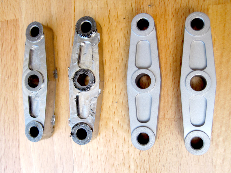
Balansarmar till fjädringssystemet, i olika stadier av bearbetning samt färdiga. The Balances of the spring system in various stages of manufacturing. |
abc |
Fräsning av en tvärbalk till ramen. Milling a crossbeam or stretcher for the frame. |
|
Två olika typer av tvärbalkar. Two different crossbeams for the frame. |
abc |
Tvärbalkarna sedda från andra sidan. The other side of the two stretchers. |
|
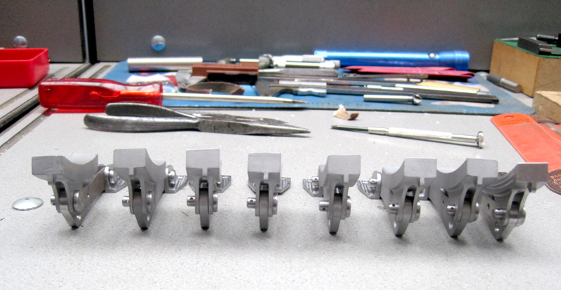
Monterade delar – upphängningsbeslag, blockhävarmar och bromsblock till tendern. Brake suspension, brake hangers and |
abc |
Samma som motstående bild, Brake assembly for the tender |
———
Del 3 — 2019–01–02 — Part 3
|
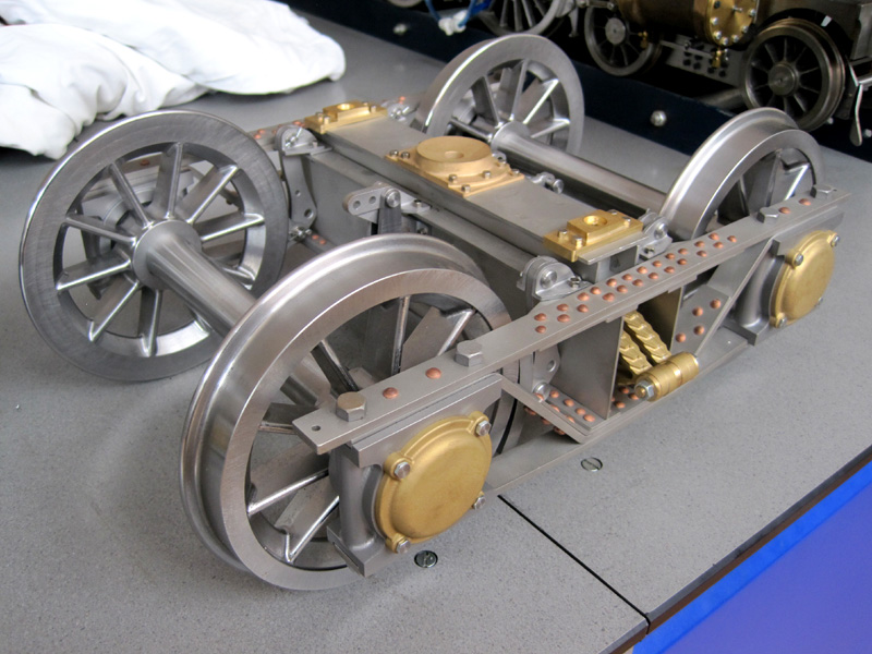
Den bärande stommen i tenderns boggi består av delar tillverkade i rostfritt material, laserskurna till rätt passform. Delar i konstruktionen vilka måste böjas tillverkas även de medelst laserskärning. Delarna som sätts samman för svetsning placeras i rätt position genom utskurna slitsar och tungor. |
abc |
The supporting construction of the tender bogie consists of stainless steel parts that The parts that had to be bend are also done The parts are assembled for welding with lip and slit joints. |
|
Skärmbild av en boggi till tendern, This is a screenshot of the CAD model |
abc |
Delarna till tenderns boggier som de ser ut levererade från laserskärningen. Vissa delar sitter redan ihopmonterade. The parts of the tender bogies as they |
|
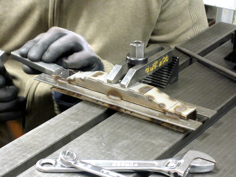
Vid svetsningen är det viktigt att delarna hålls i rätt läge på svetsbordet. Detta för att i möj-ligaste mån undvika vridningar och skevheter under själva svetsarbetet. During welding it is important to clamp the parts firmly on the welding table, in order to prevent distorting during welding, as much as possible. |
abc |
Centrala delen av boggin, den s.k. vaggbalken och omgivande I-balkar svetsas samman som en enhet. Det är också viktigt att svetsa fogarna i rätt ordning för att få den färdiga delen rak . The center construction is welded together The welding order is very significant. |
|
Vaggbalken och de omgivande I-balkarna görs i en enhet, till skillnad från originalet, Hollow section beam and I NP beams are one assembly, this in contrast to the original where the hollow section beam moves between the beams and supported by the springs. |
abc |
Centrala delarna av boggin monterade innan slutliga nitningen påbörjas.
The central parts of the bogie assembly
|
———
Del 4 — 2019–02–11 — Part 4
| Efter att de tidigare delarna i boggin monterats var det dags att nita samman alla rambalkarna med kopparnitar. Det är viktigt att göra detta i rätt ordningsföljd, eftersom vissa av nitförbanden är omöjliga att komma åt efter hand som monteringen fortskrider.Lagerboxarna sätts på plats mellan rambalkarna med genomgående långa bultar. |
abc |
When all the parts of the tender bogie were put together the frame could be assembled. This is done by means of copper rivets.The order is very important here because some rivets are no longer reachable at a later stage.Then the bearing blocks between the frame beams are mounted with long fitting bolts.
|
|
monterade lagerboxar. The riveted frame with the bearing blocks fitted. |
abc |
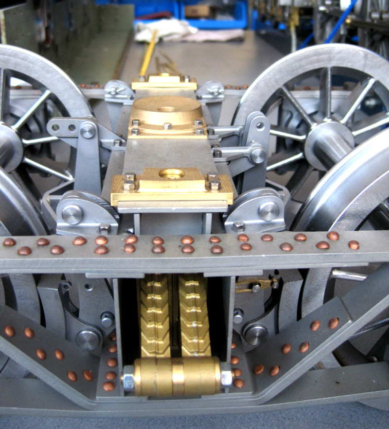
De första delarna i bromsanordningen – bromshävarmar med bromsblock och upphängningsbeslag är monterade. The first parts for the brake gear and the suspending brackets are also installed. |
|
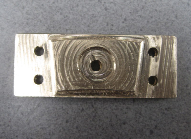
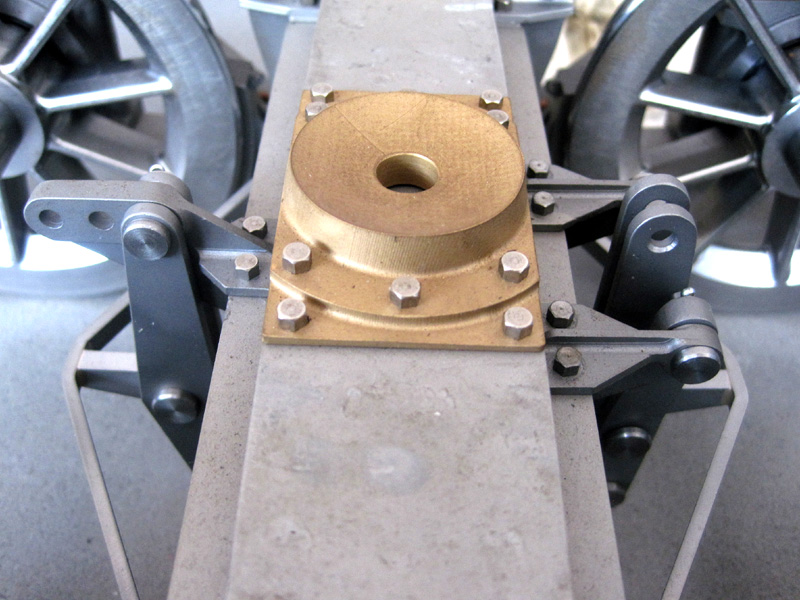
För att balansera tendern i tvärled finns två beslag, ett på vardera sidan av vaggbalken. Dessa CNC-frästa beslag gör tillsammans med två gummiblock, att boggin kan vrida sig till The CNC milled component for the transverse control of the tender frame. This part holds a rubber block which permits a certain necessary rotating movment of the bogie. |
abc |
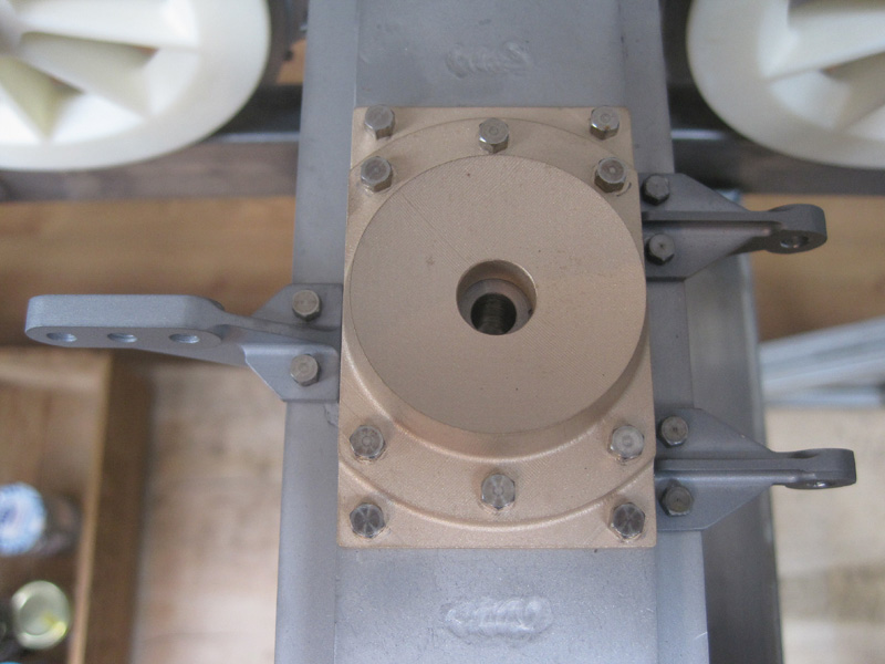
Det CNC-frästa konkava, centrala stödlagret med sin passning mot mittentappen gör att boggin kan vrida sig vid behov. The middle support and pivot point of the rotating movement of the bogie. |
|
Boggins axelboxar är CNC-frästa från två håll. Hjulen på bilden är 3D-printade i plast och kommer att ersättas med hjul i metall. Axlebox – double sided CNC milled. The wheels are 3D printed and are temporary. The steel wheels will be made later. |
abc |
Mellan blockhävarm och bromsblock syns en stabiliseringsarm, vilken gör att inte broms-blocket ligger an mot hjulet när det ej bromsas.
Between hanger and brake block a control arm is attached, which keeps the brake block in position and prevents rubbing against the wheel.
|
———
Del 5 — 2019–04–01 — Part 5
|
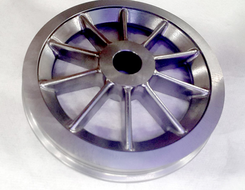
Nästa stora steg i bygget av boggierna till tendern är tillverkning av hjulen. Dessa är inte svarvade utan frästa i en CNC-fräs. Detta gör att den vackra triangelformen på hjulringens innersida kunde tillverkas. |
abc |
The next major step in the construction of the bogies is the manufacture of the wheels. The tender wheels are not turned but are completely CNC machined in the mill. Partly because of that the beautiful triangular shape of the wheel tire could be obtained. |
|
Tenderns hjul samlade på fräsmaskinens magnetbord. För säkerhets skull gjorde vi The tender wheels together on the milling machine, to be sure one extra. |
abc |
Ett hjul under fräsning på utsidan. Därefter kommer den inre halvan av hjulet att fräsas. One of the wheels during milling of the outer side. |
|
Färdigt tenderhjul, fräst på båda sidor. The wheel is ready – CNC-milled on both sides. |
abc |
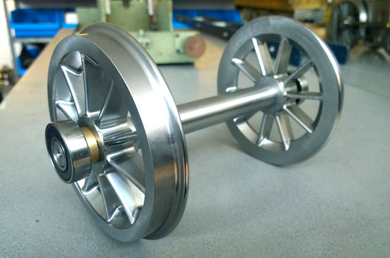
En tenderaxel med båda hjulen, distansringar samt kullager. A tender axle with both wheels, spacing sleeves and ball bearings. |
|
Hjulen säkras mot axeln medelst en tvärkil. The wheels on the axle are secured by a key. |
abc |
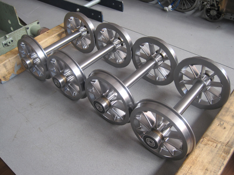
Alla fyra tenderaxlarna med lager. All four tender axels with bearings. |
|
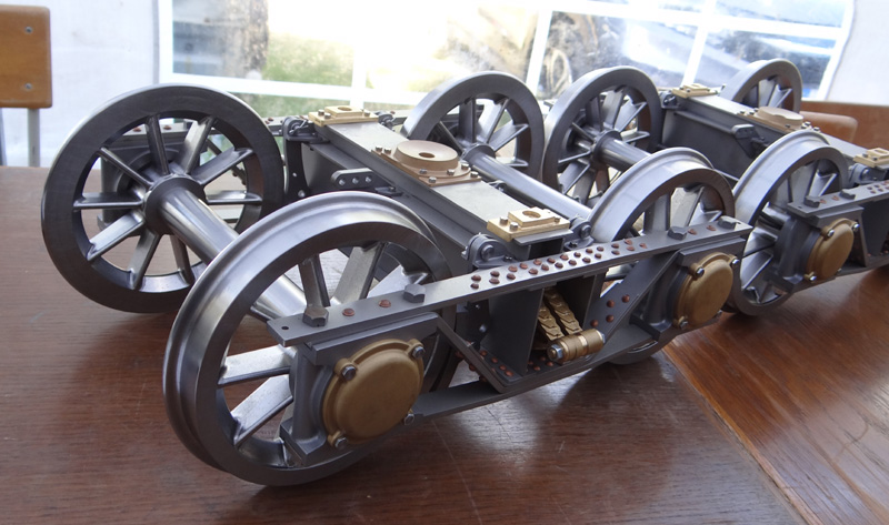
Provmontering av tenderaxlarna. The tender axels test mounted in the bogies. |
abc |
Prototypboggier visade på BMÅS 2018-08-04. Prototype bogies at the BMÅS exibition tent. |
———
Del 6 — 2019–05-10 — Part 6
|
Här har vi tillverkat en större mängd smådetaljer, som har sin plats i och på boggierna till tendern. Delarna består av fjäderpaket (attrapper) och manöverarmar för bromssystemet på boggierna. |
abc |
Finally, a large number of smaller parts have been made, all of which have a given place These are parts for the springs (dummy) and the rods for the brake system. |
|
Delar till bromssystemet. Components of the brake system. |
abc |
De CNC-frästa kedjelåsningarna, (schackel). The CNC machined D chain lock (schackle). |
|
Fräsning av fjäderattrapperna – fas 1. Milling the dummy spring package – phase 1. |
abc |
Fräsning av fjäderattrapperna – fas 2. Milling the dummy spring package – phase 2. |
|
Fräsning av fjäderattrapperna – fas 3. Milling the dummy spring package – phase 3. |
abc |
Färdiga fjäderattrapper monterade i boggi. Complete dummy spring packages in the bogie. |
|
Staget som håller bromsskon i rätt position. The spacer that holds the brake block in position. |
abc |
Alla delar på plats i mitten av boggin. All parts together in the middle of the bogie. |
|
Delar till bromssystemet på plats i boggin. Parts of the brake rigging at their position. |
abc |
Delar till bromssystemet på plats i boggin. Parts of the brake rigging at their position. |
 |
abc |
Delar till bromssystemet på plats i boggin. Parts of the brake rigging at their position.
|
———
Del 7 — 2019-06-19 — Part 7
|
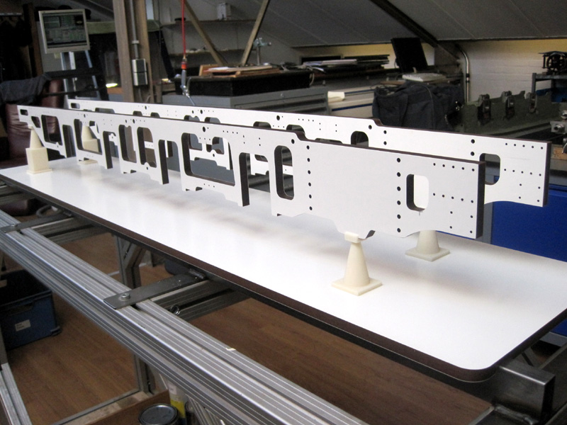
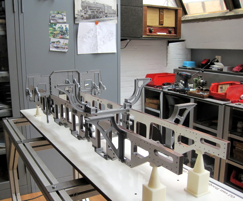
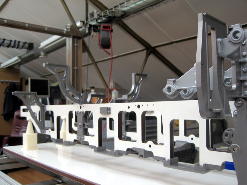
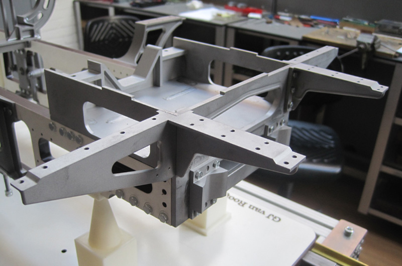
Allt eftersom flera delar blev färdiga för montering i ramverket, fann vi att cad-modellen inte var helt färdigutvecklad för slutlig tillverkning av ramsidorna. För att kunna montera alla de färdiga ramdelarna beslöt vi oss för att fräsa ut ramsidorna i ett plastmaterial för provmontering och vidareutveckling. |
abc |
After a while, more and more parts were ready for the frame, the cad model was still insufficiently worked out to fabricate the frame plates. In order to be able to assemble all those loose parts, we have decided to mill a makeshift plastic frame. |
|
Först fräses de större öppningarna ut i plasmaterialet och därefter borras alla skruvhål. First the cut-outs and the holes in the plastic plate were milled and drilled. |
abc |
Ramsidans ytterkonturer fräses fram. The outer contours of the plastic frame are milled. |
|
Speciella pallbockar för ramen skrevs ut i past-material med 3D-skrivaren. Detta gjordes för att kunna placera ramsidorna i sina rätta lägen. Support posts are printed with the 3D printer, to perfectly set up the frame. |
abc |
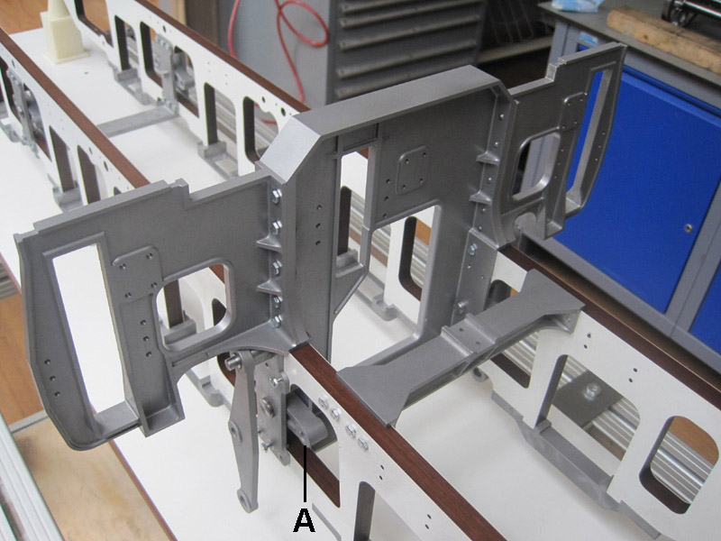
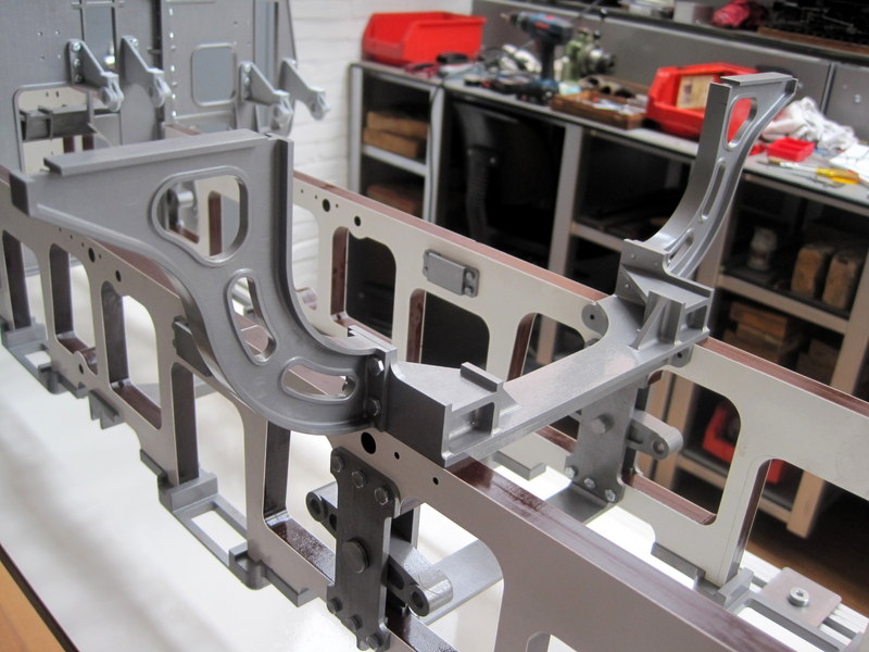
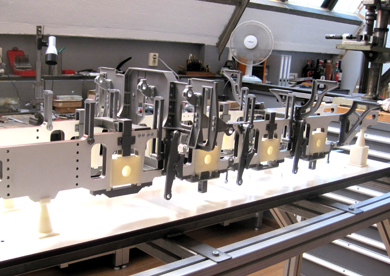
Först monteras de större rambalkarna, sidobalkarna, bindjärnen samt diverse mindre tvärstag. First, the end pieces, horn stays and various smaller cross connections were mounted. |
|
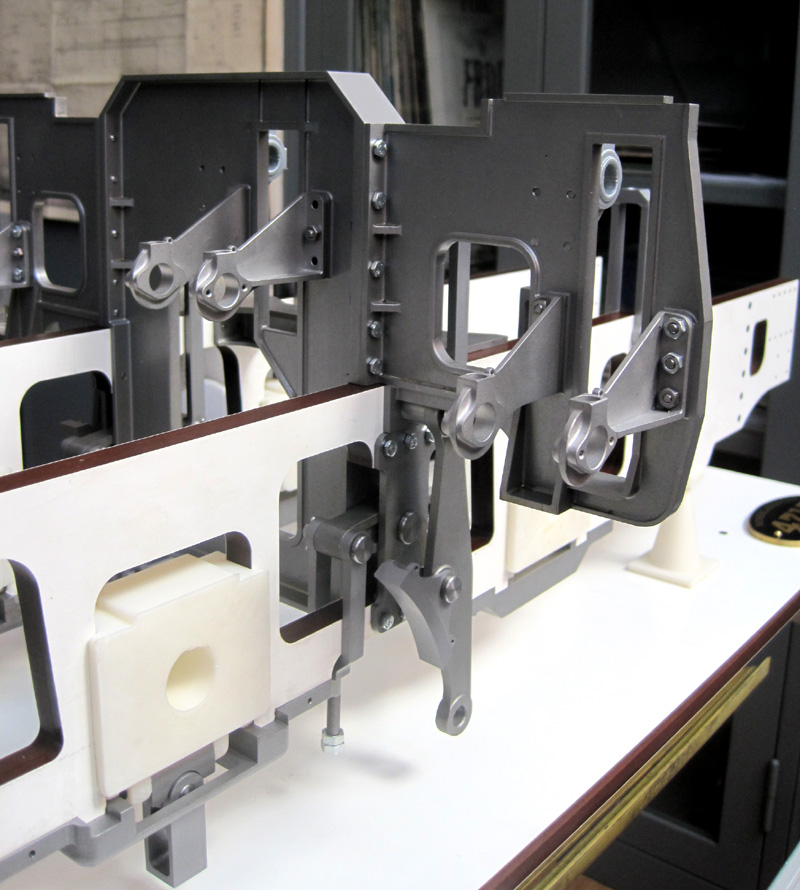
Fjädringsbalanserna (A) för hjulens fjädring och tryckutjämning syns här monterade i ramverket. (Syns bättre på föregående och nästa bild.) The balances for the suspension could then be mounted. (Better view on previous and next photo.) |
abc |
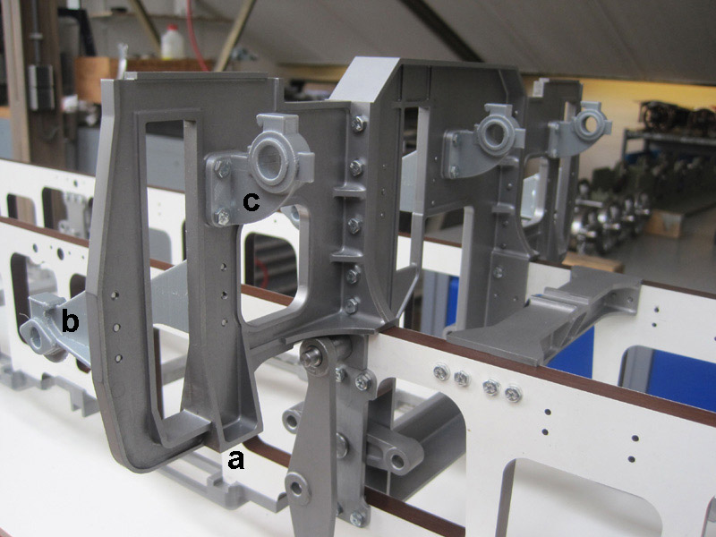
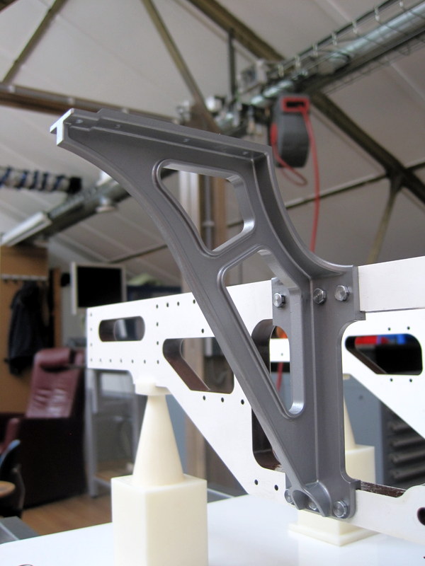
De första och största sidobalkarna är färdiga och monterade. På dessa sitter hållare för tvärstyckenas styrskenor (a), kulisserna (b) och omkastningsaxelns lagerbockar (c). In the meantime, the first larger transverse frame is ready, on which the outer slide bars (a), the expansion links (b) and the reversing shaft (c) [or weight shaft] will be mounted. |
|
abc |
Många delar 3D-printas för att först kunna kontrolleras till form och dimensioner.
Many parts are first 3D printed to check shape and dimensions.
|
———
Del 8 — 2019-08-11 — Part 8
|
Nästa steg i utvecklingen var att montera flera tvär- och sidobalkar i ramen till stöd för fyrboxen och sidobalkar för gångborden, ävensom för främre delen av hyttgolvet. |
abc |
The next step was to further fill the frame with more cross frames around the firebox, which support the front of the firebox as well as the foot plates and the front of the floor of the cab. |
|
Placeringen av tvär- och sidobalkarna framför fyrboxen ser man här bakifrån. The position of the frames around the firebox as seen from behind. |
abc |
Här ses dessa tvär- och sidobalkar framifrån. The position of the frames around the firebox as seen from the front. |
|
Denna sidobalk är placerad vid fyrboxen och hyttens golv är ligger ovanpå de två Livdelen av balken förgrenar sig runt mittre bulten (mot ramsidan) i nedre delen. This frame is located next to the firebox, the floor of the cab is supported on the top. The web of the frame is guided around the middle bolt at the bottom. |
abc |
Den sammansatta tvärbalken och de båda sidobalkarna framför fyrboxen. Balkarna bär upp gångborden. The assembly of the frame on the front of the firebox and the two frames on the outside
|
|
Bärytorna för pannans bakre glidlagringar sitter på tvärbalken, som också utgör fäste för de två sidobalkarna. The foundation for the sliding support of the boiler is located on the cross frame. |
abc |
Bilden visar även balansarmarna för fjädringen Alla dessa delar är tillverkade med CNC-teknik. The balances for the suspension can be seen. All these parts are CNC machined. |
———
Del 9 — 2019-10-19 — Part 9
|
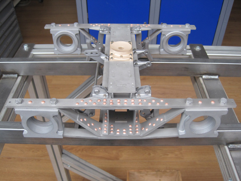
För att kunna montera alla delarna för lokets fjädring, var det nödvändigt att tillfälligt, med en 3D-skrivare, framställa lagerboxarna i provi-soriskt material. Alla andra delar i broms- och fjädersystemet är CNC-frästa i metall. |
abc |
To be able to assemble the parts for the springing system, the outer shape of the axleboxes are 3D printed. All parts of the brake and spring system were CNC machined. |
|
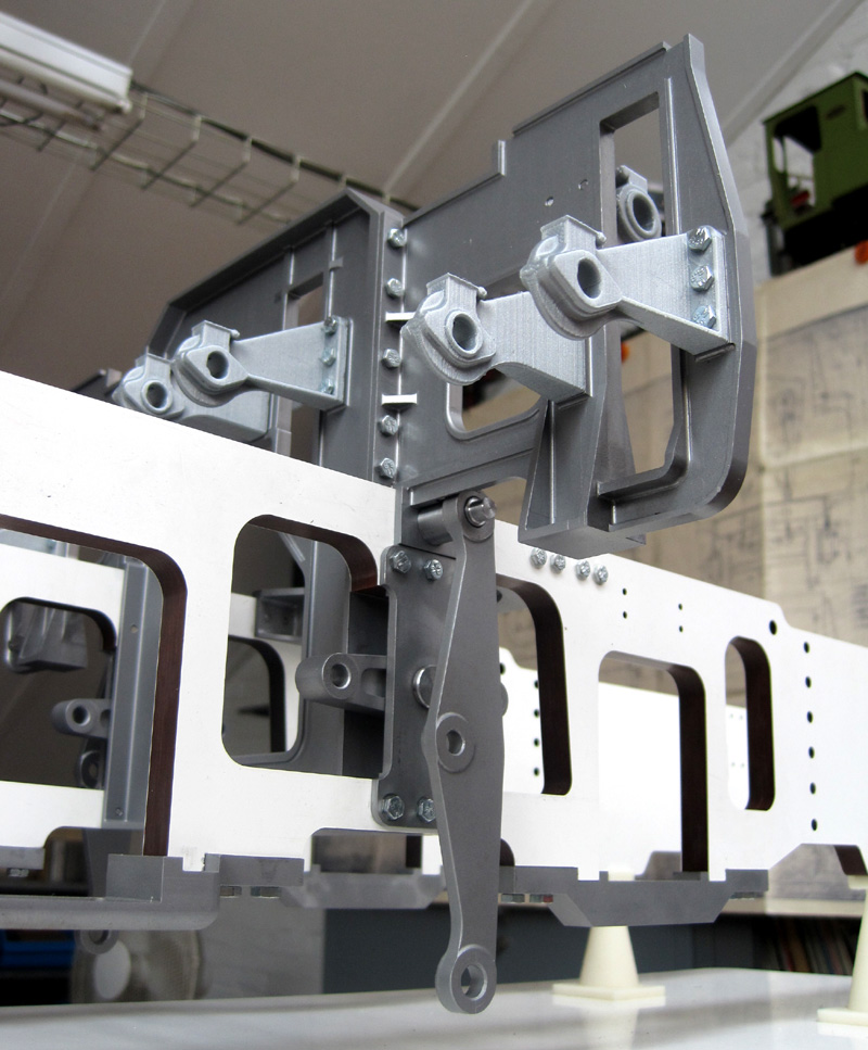
Bilden av den delvis monterade ramen visar till-hörande delar i broms- och fjädringsmekanismen. This photo of the assembly shows the components of the spring and braking system. |
abc |
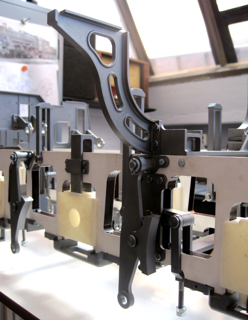
Hävarmen för denna axels bromsblock är upphängd på sidobalken, vilken även The brake hanger is suspended from the slide bar frame. |
|
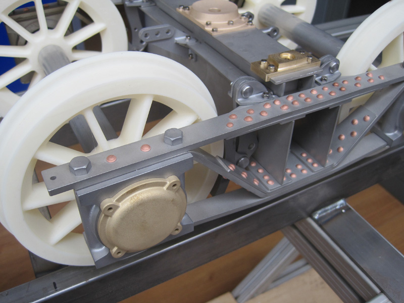
Upphängningen av bromsarmen för en The suspension of this brake hanger can be seen in this photo. At certain axleboxes the clamp for the leaf spring (under the left box) can swing towards front or rear of loco. |
abc |
Vid andra axlar däremot trycker bladfjädrarna med hjälp av en överliggande rörlig bygel på lagerboxarna. En styrning monterad på ram-sidorna håller bygeln på plats. Fjäderlänkar och balans syns tydligt, ena länken sitter ledad i ramsidan och den andra i fjäderbalansen. At other axleboxes the leaf spring press through a fork on top of the box. The fork is guided along the frame side by a milled bracket. The spring hangers and the balance are clearly visible. |
|
Upphängningen för bromsblockets hävarm samt fjäderlänken monterad i balansen. The suspension of the brake hanger is clearly visible here as well as the spring hanger. |
abc |
Ramen sedd från annan vinkel och avstånd. The assembly from different angle and distance. |
|
abc |
Bilden visar den olika utformningen In this photo you can see the different shapes of the suspension brackets
|
———
Del 10 — 2019-11-14 — Part 10
|
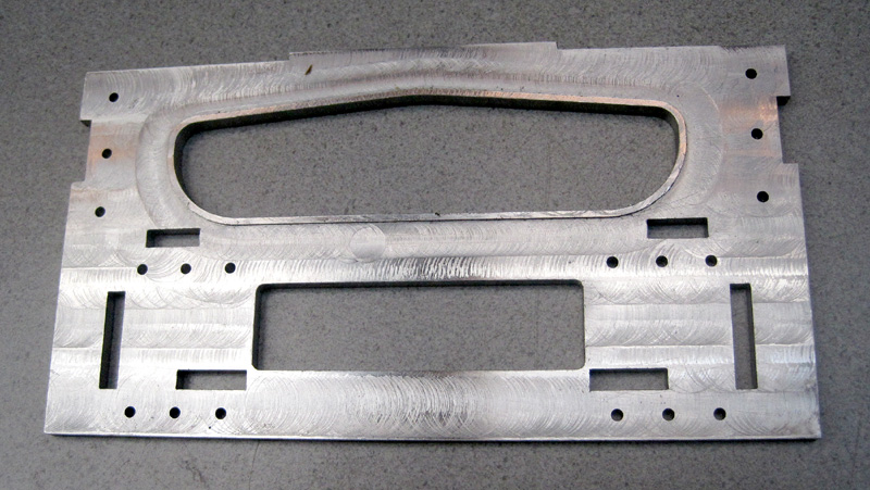
Två viktiga delar i konstruktionen av ramverket är buffertbalken och draglådan. Den senare sammanbinder ramsidorna i den bakre delen, förutom att den länkar tendern till loket. Draglådan bär även upp lokhyttens golv och den bakre delen av ångpannan. |
abc |
Two important components for assembling the frame are the buffer beam and the drag box. The drag box connects the frame plates at the rear end. The tender is linked to the locomotive via the drag box, which also supports the floor of the cab as well as the rear end of the boiler. |
|
Draglådan består av delar som är både laserskurna och CNC-frästa. The drag box is constructed by a combination of laser cut and CNC machined parts. |
abc |
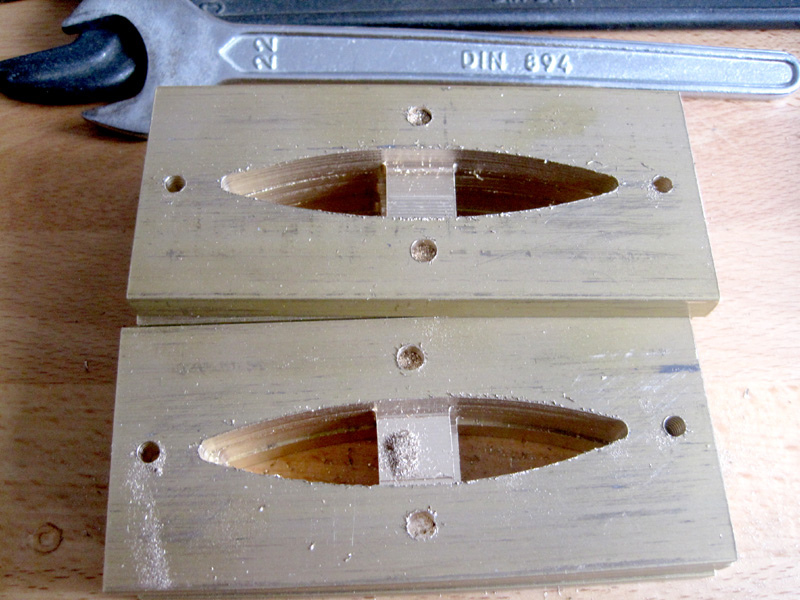
Bakre delen av ångpannan är rörligt lagrad på denna del av draglådan, men med begränsad rörlighet i höjdled. The boiler is moveably supported on this part, but restricted in the vertical direction. |
|
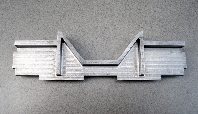
Detta är den viktigaste delen av draglådan med hålet för dragstångens bult. Den kilformiga fickan styr in dragstången till den genom hålen gående bulten. The most important part of the drag box, with the hole for the pin at the end. The angled walls guide the coupling rod to the hole. |
abc |
Bakre plåten i draglådan är CNC-fräst för att forma den förstärkande upphöjda kanten runt den övre öppningen. The back plate is CNC machined because of the edge around the upper opening. |
|
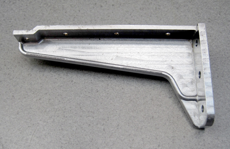
Olika konsoler (sidoramar) är fästade på draglådan som stöd för hyttgolvet. There are various consoles attached to the drag box that support the floor of the cab. |
abc |
Den uppbyggda draglådan är sammanfogad med svetsade tungor i slitsar. The assembly of the drag box. This is assembled with lips in slots and welded. |
|
Komplett draglåda monterad i den tillfälliga ramen. De olika konsolerna samt buffertplattorna för tenderns buffertar är bultade till lådan. The complete drag box in the temporary frame. The consoles and the buffer plates for the tender are bolted to the box.
|
abc |
Draglådan sedd bakifrån. Buffertplattorna är stabilt fästade vid bakre plåten medelst bultar och styrpinnar. Genom öppningen skymtar man de bakre stöden för ångpannan. Rear view of the drag box. The buffer plates are securely attached to the back plate with bolts and dowel pins. The boiler rear supports can be seen on either side through the top opening. |
Slut på del 10 — End of Part 10
Sida 2 – Del 11 till 20 / Page 2 – Part 11 to 20
|
|
abc |
